We can supply Intelligent Water Pump Controller, Water Level Induction, Pumping Remote Control, Automatic Water Tower, Water Pump, Pressure Switch
Technical Parameter
| RATED VOLTAGE | 320-380V/50-60HZ |
| LACK OF PHASE ACTION TIME | <3 SECONDS |
| SHORT CIRCUIT ACTION TIME | LESS THAN 2 SECONDS (ACTUALLY USING OVERLOAD PARAMETERS) |
| UNDER-VOLTAGE ACTION TIME | 15 SECONDS |
| UNDER-VOLTAGE RECOVERY TIME | 180 SECONDS, AND THE VOLTAGE IS HIGHER THAN THE LOW VOLTAGE THRESHOLD |
| UNDER-VOLTAGE ACTION VOLTAGE | > 280V ADJUSTABLE |
| HIGH VOLTAGE PROTECTION VOLTAGE | <480V ADJUSTABLE |
| NO-LOAD RESTART TIME | 1-999 MINUTES ADJUSTABLE (NO-LOAD PROTECTION IS DRY TO DRY TRACK PROTECTION) |
| LEVEL TRANSMISSION DISTANCE | ≤1100 METERS |
| INGRESS PROTECTION | ** |
| NETWORK TRANSMISSION | NONE |
INTRODUCTION TO THE FUNCTION OF ONE CONTROL AND TWO FUNCTIONS
Fully automated, unattended drainage system
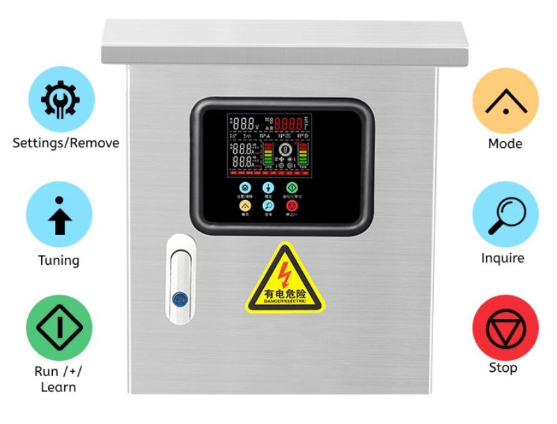
1. Control mode: manual/automatic control of 2 pumps (one for use and one for standby).
2. Manual: press the start or stop button of the No. 1 pump or No. 2 pump to realize the start and stop of the corresponding pump; When the liquid level reaches the ultra-high water level, the alarm (sound and light alarm), when the liquid level drops to the dangerous low water level, the alarm is issued, the chain protection, the two pumps stop at the same time and can not start.
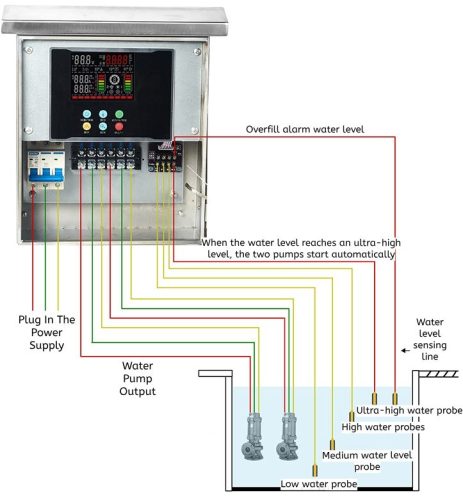
3. Automatic: When the manual/automatic transfer switch is dialed to the automatic position, the pump is controlled and alarmed by the signal transmitted by the liquid level transmitter to the controller, and the specific functions are as follows: liquid level (range: 0-1400MM): high high water level (plus pump) (95%), high water level (85%), medium water level (15%), low water level (5%). Pump control: when the liquid level reaches the high water level (plus pump), the alarm will be issued, and the two pumps will run at the same time; Start pump No. 1 when the liquid level reaches a high water level; When the liquid level drops to a low water level, the No. 1 pump stops running; When the liquid level drops to a low water level, an alarm interlocking protection is issued, and both pumps are stopped at the same time and neither can be started. When the No. 1 pump fails, an alarm will be issued to stop the current No. 1 pump, start the No. 2 pump, and the No. 1 pump will be automatically put into standby after troubleshooting, and the two pumps can be switched over and backup each other.
4. Protection and alarm: The whole control system should have short circuit, overload, phase failure and phase change protection. In the event of short circuit, overload, phase failure, and phase sequence error (this function needs to be customized), an audible and visual alarm control alarm will be issued, which can be divided into the following situations: 1. Any pump has a current overload fault; 2. Any pump has a power supply phase failure fault; 3. The liquid level is higher than the high liquid level (overflow); 4. The liquid level is lower than the low liquid level
| Settings | Function Description | Adjust by +- | |
| Press the setting key to enter (One control one) | Press the setting key to enter (One control two) | ||
| P-00 | Overvoltage | Overvoltage | Adjust by +- |
| P-01 | Undervoltage | Undervoltage | Adjust by +- |
| P-02 | A pump unloaded | A pump unloaded | Adjust by +- |
| P-03 | A pump overloaded | A pump overloaded | Adjust by +- |
| P-04 | B pump unloaded | Adjust by +- | |
| P-05 | B pump overloaded | Adjust by +- | |
| P-06 | Timed on | Timed on | Adjust by +- |
| P-07 | Timed off | Timed off | Adjust by +- |
| P-08 | Restart on no load | Restart on no load | Adjust by +- |
| P-09 | Restart on overload | Restart on overload | Adjust by +- |
| P-10 | Antirust interval | Antirust interval | Adjust by +- |
| P-11 | 485 bus address | Adjust by +- | |
| P-12 | Pump mode switch | Adjust by +- | |
| P-13 | Sensor upper and lower tank position | Adjust by +- | |
| P-14 | Sensor measuring range | Adjust by +- | |
| P-15 | Sensor stop bit | Adjust by +- | |
| P-16 | Sensor start bit | Adjust by +- | |
| P-17 | Sensor dual pump start position | Adjust by +- | |
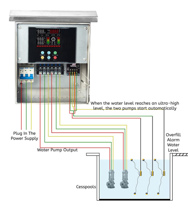
Wiring Diagram Of One Control And Two Drainage Floats
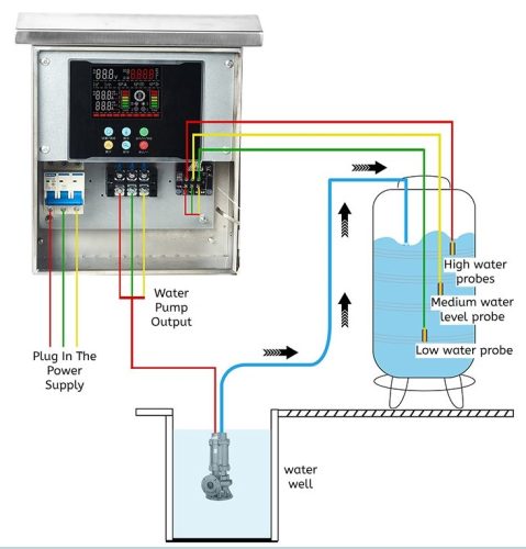
Probe Water Supply Wiring Diagram
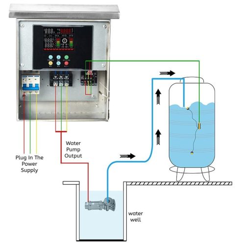
Float Water Supply Wiring Diagram
Float Drain Wiring Diagram
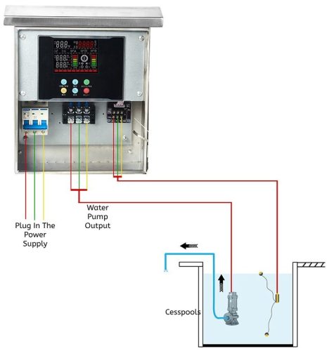
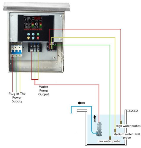
Probe Drain Wiring Diagram
One Control And Two Drainage Wiring Diagrams
Certificates
Workshop